Support Center
Introduction
While sensors continue to improve by adding more on-sensor features and greater low-light sensitivity, application engineers are still under pressure to add value as they strive to push the limits of what a camera and sensor can offer. This has typically led to engineers adding imaging post-processing that takes place on the host PC. One such popular post-processing feature implements a high dynamic range (HDR) processing pipeline for high contrast scenes, such as those in outdoor automotive applications. With the release of Sony’s IMX490 CMOS sensor, Sony has moved HDR processing on the sensor, allowing vision engineers the opportunity to streamline their HDR application while also taking advantage of LUCID’s on-camera 24-bit image processing pipeline.
Table of Contents
Introduction
High Dynamic Range: The Traditional Way
Traditional HDR: Not Great for Motion
IMX490: Simultaneous Exposures
IMX490: Flicker Mitigation
How it Works: Pixel Structure
Pixel Potential Cross Sections and Driving Sequence
Next Steps: Using LUCID’s TRI054S IMX490 in ArenaView
Video Resources
Conclusion
High Dynamic Range: The Traditional Way
HDR imaging typically requires multiple images, each with different exposure time settings, to be processed and combined into a single image. The different exposure settings allow more usable image data to be collected in the highlights and shadows. For example, longer exposure times will capture more data in the shadows at the expense of blowing out the highlights. The opposite is true for shorter exposure times, capturing more usable data in the highlights while being too short to capture any usable data in the shadows. The final processed image will take the best data from each exposure and combine it into an HDR image.
Above: Traditional HDR combines a series of multiple images, each with a different exposure time setting. These images are taken one after the other and are then processed and combined on the host PC into a single HDR image.
Side Note
Traditional HDR imaging can be done using the camera’s sequencer feature. Sequencer allows the camera to be programmed to take a series of images one after the other. Each image can have different settings, including different resolutions, gain, exposures, etc. These images can then be processed on the host PC.
Traditional HDR: Not Great for Motion
While traditional HDR imaging is great for static scenes with little to no motion, high speed scenes, such as in automotive applications, can produce motion artifacts. Motion artifacts are caused when objects in the scene change positions between different exposures. This happens because each exposure is taking place at a different time, one after the other, and this latency between the exposures causes the HDR post processing to produce a final image with objects that look morphed or warped together.
Above: Traditional HDR processing, using a sequence of multiple exposures one after the other, are not ideal for scenes with motion. This is because of the latency between each exposure is different and results in motion artifacts.
Final HDR Result, Motion Artifacts:

The resulting HDR image has severe motion artifacts. This is apparent in the distortions in the cars and the buildings.
IMX490: Simultaneous Exposures
Unlike traditional HDR processing, Sony’s IMX490 CMOS sensor does not have any latency between exposures. In fact, all exposures are set to the same length and take place at the same time. This is possible thanks to the sensor’s sub-pixel technology (also known as split-pixel technology) where the sensor contains both large and small pixels, with each pixel size having a different light sensitivity. In addition, each sub-pixel is readout with high and low conversion gains giving four 12-bit channels for each pixel. These four channels are then processed on-sensor and combined into single linear 24-bit HDR value. (Note: While it is possible to change each pixel’s exposure length between the large and small pixels, it is recommended that they be kept the same).
Above: Sony’s IMX490 sensor not only has 2 different size pixels (1 large, 1 small) but also each pixel has 2 channel outputs (high gain, low gain). This allows for a total of 4 exposures to happen simultaneously.
Above: The data from the 4 channels are combined on-sensor into one 24-bit HDR image
IMX490: Flicker Mitigation
An additional benefit of having simultaneous exposures with the sub-pixels on the IMX490 is LED flicker mitigation. Many conventional HDR cameras must use very short exposure times to measure low sensitivity data in bright scenes to avoid oversaturating the photodiodes. Unfortunately, these short exposures can be short enough to capture LED flickering – fast voltage variations in LED power sources which cause the LEDs to quickly alternate between on and off, resulting in video that shows LED flashing on and off. But because of the sub-pixel technology, the IMX490 does not need to use these very short exposure times. The specific sub-pixel which is more sensitive to bright areas, can be set to the same longer exposure as the other pixels, allowing the sensor to average out the flicker.
Above: Very short exposure times can capture AC LED flicker at 30, 50 or 60 Hz. But thanks to the IMX490’s low sensitivity sub-pixel, the IMX490 can operate at longer exposure times, averaging out the flicker.
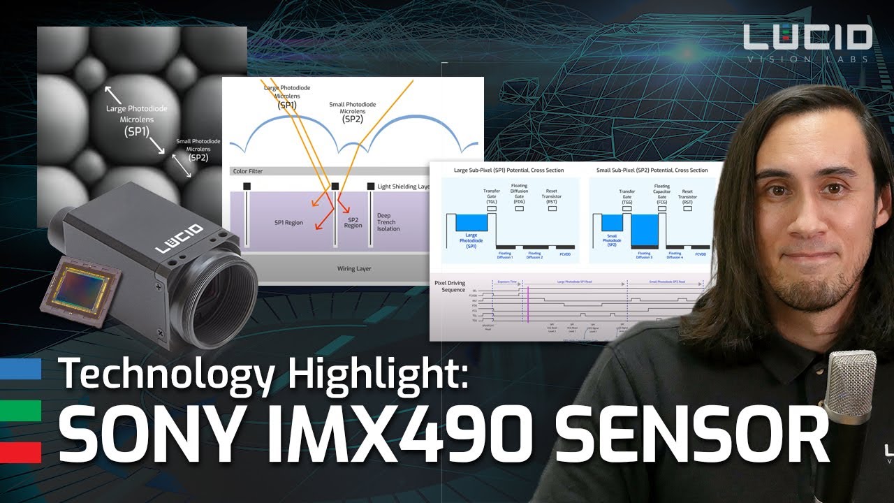
How it Works: Pixel Structure
The design of the sensor includes technologies that improve overall sensitivity while reducing image noise. The IMX490 is a back-illuminated (BSI) sensor, with the wiring layer below the photodiode. This results in better sensitivity by allowing more light to reach the photodiode without being obstructed by the circuit wiring. Each sub-pixel also has a different sized microlens, to better focus light into their respective photodiodes. A light shield is implemented, along with a deep trench to help isolate each pixel from optical cross-talk and electrical charge leakage between the two sub pixels. This design results in high quantum efficiency, dynamic range over 120dB, with a combined sub-pixel saturation capacity of 120000 e-.
Above: Zooming into the sensor reveals two different size pixels
Close-up view of the two sub-pixels (simulated image)
Cross sectional view of the pixel structure. The IMX490 is a BSI, rolling shutter CMOS sensor.
Interactive graphs – please hover over the points in the graph to reveal QE %
| Color EMVA 1288 Results | |
|---|---|
| Dynamic Range | 123.6 dB |
| SNR (Max) | 50.8 dB |
| Saturation Capacity | 120000 e- |
| Absolute Sensitivity Threshold (Measured at 527.5nm) | 1.5 γ |
| Temporal Dark Noise | 0.54 e- |
| Gain | 9.83 DN24 / e- |
![]()
EMVA 1288 is the Standard for Measurement and Presentation of Specifications for Machine Vision Sensors and Cameras. For more information of the EMVA 1288 standard please visit http://www.emva.org/standards-technology/emva-1288/
Pixel Potential Cross Sections and Driving Sequence
The unique design of the IMX490 incorporates multiple floating diffusions for both sub-pixel 1 (SP1) and sub-pixel 2 (SP2). While the exposures occur simultaneously, the signals from SP1 and SP2 are output serially. The animation below displays the various stages to the pixel potentials along with the pixel driving sequence.
Stages:
8) All Electrical charges in SP1 and SP2 are reset.
1) Exposure: Both sub-pixels (SP1 and SP2) are exposed at the same time.
SP1 Readout:
2) SP1 Reset levels for low and high gain are sampled.
3) Signal for SP1 high conversion gain is sampled.
4) Signal for SP1 low conversion gain is sampled.
* Because SP1’s reset and signal levels are sampled, this sub-pixel can perform Correlated Double Sampling (CDS) for noise reduction.
SP2 Readout:
5) SP2’s high conversion gain is sampled.
6) SP2’s low conversion gain is sampled.
7) SP2’s Reset level is sampled.
* Because reset sampling is done after SP2’s signals, SP2 can not do CDS. Instead, SP2 uses Delta Reset Sampling for noise suppression.
8) All Electrical charges in SP1 and SP2 are reset.
Next Steps: Using LUCID’s TRI054S IMX490 in ArenaView
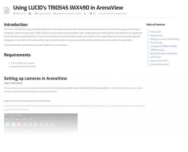
For those looking for instructions on how to use the TRI054S-CC in LUCID’s ArenaView, please visit our KB Article: Using LUCID’s TRI054S IMX490 in ArenaView
This KB article explains the various features and options available on the TRI054S-CC including HDR Tuning, Image Enhancement, Digital Clamping, and more. In addition, the article includes instructions on changing the bit depth display, adjusting the LUT, and switching the Tone Mapping Gamma.
Video Resources
Conclusion
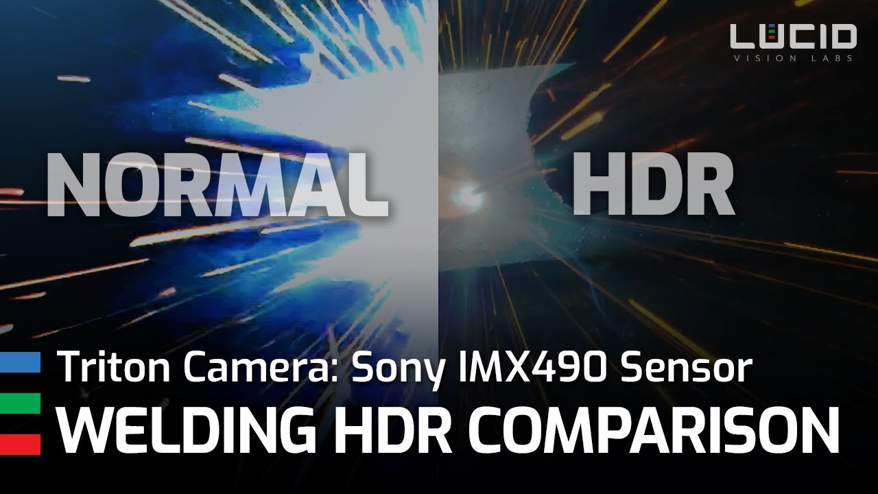
Pairing Sony’s IMX490 with LUCID’s Triton IP67 camera provides 120 dB high dynamic range imaging that is well suited for challenging applications that contain both very dark and bright areas in the scene. The IMX490 achieves this through its sub-pixel technology with dual channel output, providing 4 simultaneous exposures resulting in clear, distortion free imaging without motion artifacts. In addition, thanks to the simultaneous exposures, the camera is able to reduce LED flicker by allowing for longer exposures times compared to conventional HDR cameras that required shorter exposures. LUCID’s Triton camera features a 24-bit ISP that allows users to access and fine tune all the features the IMX490 sensor has to offer. Thanks also to the camera’s IP67 Factory Tough™ design, the Triton 5.4MP camera is perfectly suited for outdoor applications such as advanced driver assistance systems(ADAS) or autonomous driving, along with industrial applications such as live welding inspection.
To see pricing or order online visit our Triton 5.4MP IMX490 product page.